In recent years, improvements in the efficiency of photovoltaic water pumping systems (PVWPS) have attracted great interest among researchers, as their operation is based on clean electrical energy production.In this paper, a new fuzzy logic controller-based approach is developed for PVWPS applications that incorporates loss minimization techniques applied to induction motors (IM).The proposed control selects the optimal flux magnitude by minimizing IM losses.In addition, the variable-step perturbation observation method is also introduced.The suitability of the proposed control is recognized by reducing the sink current; therefore, motor losses are minimized and efficiency is improved.The proposed control strategy is compared with methods without loss minimization.The comparison results illustrate the effectiveness of the proposed method, which is based on the minimization of losses in electrical velocity, absorbed current, flowing water, and developing flux.A processor-in-the-loop (PIL) test is performed as an experimental test of the proposed method.It includes the implementation of the generated C code on the STM32F4 discovery board.The results obtained from the embedded board are similar to the numerical simulation results.
Renewable energy, especially solar photovoltaic technology, can be a cleaner alternative to fossil fuels in water pumping systems1,2.Photovoltaic pumping systems have received considerable attention in remote areas without electricity3,4.
Various engines are used in PV pumping applications.The primary stage of PVWPS is based on DC motors.These motors are easy to control and implement, but they require regular maintenance due to the presence of the annotators and brushes5.To overcome this shortcoming, brushless permanent magnet motors were introduced, which are characterized by brushless, high efficiency and reliability6.Compared to other motors, IM-based PVWPS has better performance because this motor is reliable, low-cost, maintenance-free, and offers more possibilities for control strategies7.Indirect Field Oriented Control (IFOC) techniques and Direct Torque Control (DTC) methods are commonly used8.
IFOC was developed by Blaschke and Hasse and allows changing the IM speed over a wide range9,10.The stator current is divided into two parts, one generates the magnetic flux and the other generates the torque by converting to the dq coordinate system.This allows independent control of flux and torque under steady state and dynamic conditions.Axis (d) is aligned with the rotor flux space vector, which involves the q-axis component of the rotor flux space vector being always zero.FOC provides a good and faster response11,12, however, this method is complex and subject to parameter variations13.To overcome these shortcomings, Takashi and Noguchi14 introduced DTC, which has high dynamic performance and is robust and less sensitive to parameter changes.In DTC, the electromagnetic torque and stator flux are controlled by subtracting the stator flux and torque from the corresponding estimates.The result is fed into a hysteresis comparator to generate the appropriate voltage vector to control both stator flux and torque.
The main inconvenience of this control strategy is the large torque and flux fluctuations due to the use of hysteresis regulators for stator flux and electromagnetic torque regulation15,42.Multilevel converters are used to minimize ripple, but efficiency is reduced by the number of power switches16.Several authors have used space vector modulation (SWM)17, sliding mode control (SMC)18, which are powerful techniques but suffer from undesirable jittering effects19.Many researchers have used artificial intelligence techniques to improve controller performance, among them, (1) neural networks, a control strategy that requires high-speed processors to implement20, and (2) genetic algorithms21.
Fuzzy control is robust, suitable for nonlinear control strategies, and does not require knowledge of the exact model.It includes the use of fuzzy logic blocks instead of hysteretic controllers and switch selection tables to reduce flux and torque ripple.It is worth pointing out that FLC-based DTCs provide better performance22, but not enough to maximize the efficiency of the engine, so control loop optimization techniques are required.
In most previous studies, the authors chose constant flux as the reference flux, but this choice of reference does not represent optimal practice.
High-performance, high-efficiency motor drives require fast and accurate speed response.On the other hand, for some operations, the control may not be optimal, so the efficiency of the drive system cannot be optimized.Better performance can be obtained by using a variable flux reference during system operation.
Many authors have proposed a search controller (SC) that minimizes losses under different load conditions (such as in27) to improve the efficiency of the engine.The technique consists of measuring and minimizing the input power by iterative d-axis current reference or stator flux reference.However, this method introduces torque ripple due to oscillations present in the air-gap flux, and the implementation of this method is time-consuming and computationally resource-intensive.Particle swarm optimization is also used to improve efficiency28, but this technique can get stuck in local minima, leading to poor selection of control parameters29.
In this paper, a technique related to FDTC is proposed to select the optimal magnetic flux by reducing motor losses.This combination ensures the ability to use the optimal flux level at each operating point, thereby increasing the efficiency of the proposed photovoltaic water pumping system.Therefore, it seems to be very convenient for photovoltaic water pumping applications.
Furthermore, a processor-in-the-loop test of the proposed method is performed using the STM32F4 board as an experimental validation.The main advantages of this core are simplicity of implementation, low cost and no need to develop complex programs 30 .In addition, the FT232RL USB-UART conversion board is associated with the STM32F4, which guarantees an external communication interface in order to establish a virtual serial port (COM port) on the computer.This method allows data to be transmitted at high baud rates.

The performance of PVWPS using the proposed technique is compared with PV systems without loss minimization under different operating conditions.The obtained results show that the proposed photovoltaic water pump system is better in minimizing stator current and copper losses, optimizing flux and pumping water.
The rest of the paper is structured as follows: The modeling of the proposed system is given in the section “Modeling of Photovoltaic Systems”.In the section “Control strategy of the studied system”, FDTC, the proposed control strategy and MPPT technique are described in detail.The findings are discussed in the “Simulation Results” section.In the “PIL testing with the STM32F4 discovery board” section, processor-in-the-loop testing is described.The conclusions of this paper are presented in the “Conclusions” section.
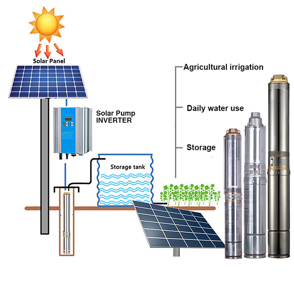
Figure 1 shows the proposed system configuration for a stand-alone PV water pumping system.The system consists of an IM-based centrifugal pump, a photovoltaic array, two power converters [boost converter and voltage source inverter (VSI)].In this section, the modeling of the studied photovoltaic water pumping system is presented.
This paper adopts the single-diode model of solar photovoltaic cells.The characteristics of the PV cell are denoted by 31, 32, and 33.
To perform the adaptation, a boost converter is used.The relationship between the input and output voltages of the DC-DC converter is given by Equation 34 below:
The mathematical model of IM can be described in the reference frame (α,β) by the following equations 5,40:
Where \(l_{s }\),\(l_{r}\): stator and rotor inductance, M: mutual inductance, \(R_{s }\), \(I_{s }\): stator resistance and stator Current, \(R_{r}\), \(I_{r }\): rotor resistance and rotor current, \(\phi_{s}\), \(V_{s}\): stator flux and stator voltage , \(\phi_{r}\), \(V_{r}\): rotor flux and rotor voltage.
The centrifugal pump load torque proportional to the square of the IM speed can be determined by:
The control of the proposed water pump system is divided into three distinct subsections.The first part deals with MPPT technology.The second part deals with driving the IM based on the fuzzy logic controller’s direct torque control.Furthermore, Section III describes a technique related to FLC-based DTC that allows the determination of reference fluxes.
In this work, a variable-step P&O technique is used to track the maximum power point.It is characterized by fast tracking and low oscillation (Figure 2)37,38,39.
The main idea of DTC is to directly control the flux and torque of the machine, but the use of hysteresis regulators for electromagnetic torque and stator flux regulation results in high torque and flux ripple.Therefore, a blurring technique is introduced to enhance the DTC method (Fig. 7), and the FLC can develop sufficient inverter vector states.
In this step, the input is transformed into fuzzy variables through membership functions (MF) and linguistic terms.
The three membership functions for the first input (εφ) are negative (N), positive (P), and zero (Z), as shown in Figure 3.
The five membership functions for the second input (\(\varepsilon\)Tem) are Negative Large (NL) Negative Small (NS) Zero (Z) Positive Small (PS) and Positive Large (PL), as shown in Figure 4.
The stator flux trajectory consists of 12 sectors, in which the fuzzy set is represented by an isosceles triangular membership function, as shown in Figure 5.
Table 1 groups 180 fuzzy rules that use the input membership functions to select appropriate switch states.
The inference method is performed using Mamdani’s technique.The weight factor (\(\alpha_{i}\)) of the i-th rule is given by:
where\(\mu Ai \left( {e\varphi } \right)\),\(\mu Bi\left( {eT} \right) ,\) \(\mu Ci\left( \theta \right) \) : Membership value of magnetic flux, torque and stator flux angle error.
Figure 6 illustrates the sharp values obtained from the fuzzy values using the maximum method proposed by Eq.(20).
By increasing the motor efficiency, the flow rate can be increased, which in turn increases the daily water pumping (Figure 7).The purpose of the following technique is to associate a loss minimization based strategy with a direct torque control method.
It is well known that the value of the magnetic flux is important for the efficiency of the motor.High flux values lead to increased iron losses as well as magnetic saturation of the circuit.Conversely, low flux levels result in high Joule losses.
Therefore, the reduction of losses in IM is directly related to the choice of flux level.
The proposed method is based on the modeling of the Joule losses associated with the current flowing through the stator windings in the machine.It consists of adjusting the value of the rotor flux to an optimum value, thereby minimizing motor losses to increase efficiency.Joule losses can be expressed as follows (ignoring core losses):
The electromagnetic torque\(C_{em}\) and rotor flux\(\phi_{r}\) are calculated in the dq coordinate system as:
The electromagnetic torque\(C_{em}\) and rotor flux\(\phi_{r}\) are calculated in reference (d,q) as:
by solving the equation.(30), we can find the optimal stator current that ensures optimal rotor flux and minimal losses:
Different simulations were performed using MATLAB/Simulink software to evaluate the robustness and performance of the proposed technique.The investigated system consists of eight 230 W CSUN 235-60P panels (Table 2) connected in series.The centrifugal pump is driven by IM, and its characteristic parameters are shown in Table 3.The components of the PV pumping system are shown in Table 4.
In this section, a photovoltaic water pumping system using FDTC with a constant flux reference is compared with a proposed system based on optimal flux (FDTCO) under the same operating conditions.The performance of both photovoltaic systems was tested by considering the following scenarios:
This section presents the proposed start-up state of the pump system based on an insolation rate of 1000 W/m2.Figure 8e illustrates the electrical velocity response.Compared with FDTC, the proposed technique provides a better rise time, reaching steady state at 1.04 s, and with FDTC, reaching steady state at 1.93 s.Figure 8f shows the pumping of the two control strategies.It can be seen that the FDTCO increases the pumping amount, which explains the improvement in the energy converted by the IM.Figures 8g and 8h represent the drawn stator current.The startup current using the FDTC is 20 A, while the proposed control strategy suggests a startup current of 10 A, which reduces Joule losses.Figures 8i and 8j show the developed stator flux.The FDTC-based PVPWS operates at a constant reference flux of 1.2 Wb, while in the proposed method, the reference flux is 1 A, which is involved in improving the efficiency of the photovoltaic system.
(a) Solar radiation (b) Power extraction (c) Duty cycle (d) DC bus voltage (e) Rotor speed (f) Pumping water (g) Stator phase current for FDTC (h) Stator phase current for FDTCO (i) Flux response using FLC (j) Flux response using FDTCO (k) Stator flux trajectory using FDTC (l) Stator flux trajectory using FDTCO.
The solar radiation varied from 1000 to 700 W/m2 at 3 seconds and then to 500 W/m2 at 6 seconds (Fig. 8a).Figure 8b shows the corresponding photovoltaic power for 1000 W/m2, 700 W/m2 and 500 W/m2.Figures 8c and 8d illustrate the duty cycle and DC link voltage, respectively.Figure 8e illustrates the electrical speed of IM, and we can notice that the proposed technique has better speed and response time compared to the FDTC-based photovoltaic system.Figure 8f shows the water pumping for different irradiance levels obtained using FDTC and FDTCO.More pumping can be achieved with FDTCO than with FDTC.Figures 8g and 8h illustrate the simulated current responses using the FDTC method and the proposed control strategy.By using the proposed control technique, the current amplitude is minimized, which means less copper losses, thus increasing system efficiency.Therefore, high start-up currents can lead to reduced machine performance.Figure 8j shows the evolution of the flux response in order to select the optimal flux to ensure that losses are minimized, therefore, the proposed technique illustrates its performance.In contrast to Figure 8i, the flux is constant, which does not represent optimal operation.Figures 8k and 8l show the evolution of the stator flux trajectory.Figure 8l illustrates the optimal flux development and explains the main idea of the proposed control strategy.
A sudden change in solar radiation was applied, starting with an irradiance of 1000 W/m2 and abruptly decreasing to 500 W/m2 after 1.5 s (Fig. 9a).Figure 9b shows the photovoltaic power extracted from the photovoltaic panels, corresponding to 1000 W/m2 and 500 W/m2.Figures 9c and 9d illustrate the duty cycle and DC link voltage, respectively.As can be seen from Fig. 9e, the proposed method provides better response time.Figure 9f shows the water pumping obtained for the two control strategies.Pumping with FDTCO was higher than with FDTC, pumping 0.01 m3/s at 1000 W/m2 irradiance compared to 0.009 m3/s with FDTC; furthermore, when irradiance was 500 W At /m2, FDTCO pumped 0.0079 m3/s, while FDTC pumped 0.0077 m3/s.Figures 9g and 9h.Describes the current response simulated using the FDTC method and the proposed control strategy.We can note that the proposed control strategy shows that the current amplitude is reduced under abrupt irradiance changes, resulting in reduced copper losses.Figure 9j shows the evolution of the flux response in order to choose the optimal flux to ensure that losses are minimized, therefore, the proposed technique illustrates its performance with a flux of 1Wb and an irradiance of 1000 W/m2, while The flux is 0.83Wb and the irradiance is 500 W/m2.In contrast to Fig. 9i, the flux is constant at 1.2 Wb, which does not represent optimal function.Figures 9k and 9l show the evolution of the stator flux trajectory.Figure 9l illustrates the optimal flux development and explains the main idea of the proposed control strategy and the improvement of the proposed pumping system.
(a) Solar radiation (b) Extracted power (c) Duty cycle (d) DC bus voltage (e) Rotor speed (f) Water flow (g) Stator phase current for FDTC (h) Stator phase current for FDTCO (i) ) Flux response using FLC (j) Flux response using FDTCO (k) Stator flux trajectory using FDTC (l) Stator flux trajectory using FDTCO.
A comparative analysis of the two technologies in terms of flux value, current amplitude and pumping is shown in Table 5, which shows that the PVWPS based on the proposed technology provides high performance with increased pumping flow and minimized amplitude current and losses, which is due to optimal flux selection.
To verify and test the proposed control strategy, a PIL test is performed based on the STM32F4 board.It includes generating code that will be loaded and run on the embedded board.The board contains a 32-bit microcontroller with 1 MB Flash, 168 MHz clock frequency, floating point unit, DSP instructions, 192 KB SRAM.During this test, a developed PIL block was created in the control system containing the generated code based on the STM32F4 discovery hardware board and introduced in the Simulink software.The steps to allow PIL tests to be configured using the STM32F4 board are shown in Figure 10.
Co-simulation PIL testing using STM32F4 can be used as a low-cost technique to verify the proposed technique.In this paper, the optimized module that provides the best reference flux is implemented in the STMicroelectronics Discovery Board (STM32F4).
The latter is executed concurrently with Simulink and exchanges information during co-simulation using the proposed PVWPS method.Figure 12 illustrates the implementation of the optimization technology subsystem in STM32F4.
Only the proposed optimal reference flux technique is shown in this co-simulation, as it is the main control variable for this work demonstrating the control behavior of a photovoltaic water pumping system.
Post time: Apr-15-2022


